Motor Freewheel Repair
This repair entails handling gears covered in black grease, so to avoid risk of contracting dermatitis it's advisable before starting the job to either use barrier cream or disposable vinyl gloves. The latter are sold in low cost packs of 10 or 20 by main supermarkets.
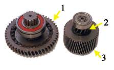
With your motor casing already opened, withdraw the cluster of gears 2 and 3, gear 1 having to come out with it. Put aside gear one assembly.
Scrape off the surplus grease from gears 2 and 3 and place it somewhere clean ready for reuse. Then wipe the gear and bearing assembly reasonably clean.
Scrape off the surplus grease from gears 2 and 3 and place it somewhere clean ready for reuse. Then wipe the gear and bearing assembly reasonably clean.
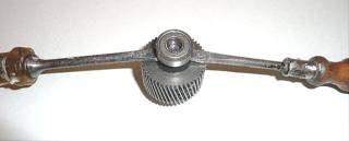
Now you need to remove the bearing at the opposite end to gear 2. Use a thin jaw puller if you have one, but if not use a pair of strong screwdrivers as shown and press down evenly on the handles to slide the bearing upon the shaft. You may need a thick object under the gear assembly to get full removal.
With the bearing off, you'll see a small circlip on the shaft, so remove that, then remove the black washer underneath and you will be able to lift gear 3 off from gear 2's shaft.
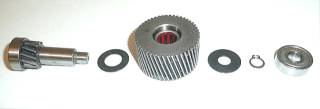
Here's all the components you'll now see, here in the order of re-assembly from left to right. Inside the gear you can see needle rollers in a red cage. These are against tiny ramps in the gearwheel, and turning the shaft against the ramp direction causes the rollers to run up the
ramps and lock the shaft in the gear. Turning in the opposite direction allows the shaft to turn freely inside the gear. The act of stripping the assembly has cured the fault, so you can now go to re-assembly. Work from left to right in the photgraph above, but note this:
The gear with it's needle rollers must go back on the way it came off to get the freewheel action in the correct direction. To check this, after sliding the first washer and gear 3 onto the shaft, hold the small gear 2 with your left hand and try to turn gear 3. The top of the large gear 3 as you look down on it should turn freely away from you, but be locked if you try to turn it towards you.
With that correct, replace the small centre hole washer and then the circlip. Finally replace the bearing. To do that you can evenly press it back on with a vice or place a piece of flat wood or rigid plastic on the bearing and gently tap it back on with a hammer. Re-assemble the gears pair into the motor unit, you'll need to slide them in together, and then wipe the reserved grease onto the gear teeth surfaces.
No reason for locking up has been seen in the very few cases to date, but there are two possibilities. First, a small flake of metal jamming a roller up a ramp, or second but unlikely, the wear in the ramp surfaces allowing the rollers to lock at the topmost point.
Gear 2 shaft will be locked inside gear 3 at this point, but try wiggling one against the other and see if they free up, allowing the shaft to turn inside gear 3 in one direction. If that's successful you can reassemble the unit. If not, proceed with the following next.
Replacing the Motor Shaft Bearings
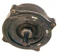
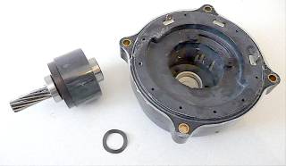
Part the crankcase and disconnect the larger of the two white connectors from the circuit board. Unbolt the motor from the crankcase, disconnect all three heavy wire connections connections from the tags and withdraw the Hall sensor board wires with the large white connector from the crankcase. Remove the two rubber securing washers and the Hall sensor board from the locating pegs on the motor face to leave the motor as you see it here at the right.
Scrape the surplus grease from the spiral gear teeth of the motor shaft and retain it. Now thoroughly clean the shaft surface, grasp it and pull it up from the housing against the very strong magnetic pull of the rotor. You may need to use a cloth or rubber gloves to get enough grip. If you do use a gripping tool of any kind, take great care not to damage the shaft's spiral teeth.
Use a puller to withdraw the bearing you want to replace, or if you haven't got one, lever out the bearing using the two screwdriver method shown for the freewheel bearing removal. Press evenly on both sides and take care not to damage the rotor.
While you have the rotor stripped out, note the tiny dimensions of this motor. The stator windings assembly is just 85 mm in diameter, the magnetic rotor 45 mm in diameter and the motor width just 23 mm.
When reassembling after pressing on a new bearing, place the spring washer seen in the photo above in the light coloured recess shown at the rear of the casing, then lower the rotor vertically down into the stator casing to prevent the spring washer being attracted onto the magnetic rotor. Apply the grease you reserved onto the spiral teeth of the shaft at a convenient point as you reassemble the unit.
29.4.2008
.