Lafree/Lite Technical Information
If you want to change the overall gearing of your bike, you can do it by changing the sprocket on the hub gear. Below you'll see the ranges you'll get in gear inches in the lowest and highest gears and the top assisted speed with various sprocket sizes. The red line is the normal gearing for rough compliance with European law, those above it make the bike faster at the cost of hill climbing ability, those below make the bike capable of steeper hills at the cost of speed. The maximum assisted speed is rather theoretical due to the way the power gradually phases down up to the inbuilt limit, making the exact cutoff point difficult to discern with any accuracy.
3 speed Nexus hub 5 speed SRAM hub
14 tooth, 48", 90", 17.7 mph 15 tooth, 39", 98", 17.5 mph
15 tooth, 45", 84", 16.3 mph 16 tooth, 36", 92", 16.8 mph
16 tooth, 42", 79", 15.3 mph 17 tooth, 34", 86", 15.7 mph
17 tooth, 40", 74", 14.3 mph 18 tooth, 32", 82", 14.9 mph
18 tooth, 38", 70", 13.6 mph 19 tooth, 31", 77", 14.1 mph
These are ranges which will cover any eventuality in hill climbing, or conversely, take you to a realistic maximum that a 390 watt motor can deliver most of the time.
However, here's more extreme examples of what happens with smaller sprockets, this time just with the SRAM P5 hub, supplementing the right hand list above:
gears........1st....2nd....3rd....4th....5th
14 tooth....42.....52.....66......85....105....cutoff speed 18.7 mph
13 tooth....45.....56.....71......92....113....cutoff speed 20.2 mph
The downside is that the range would drop markedly since the bike would be using more power at every speed above 13 mph because of the later power phase down commencement, and virtually always using power when riding since the bike would rarely be above the higher cutoff speeds.
Sprockets smaller than 16 tooth need to be dished (offset) to avoid the chain fouling the hub, and these are currently very difficult to find. I don't know of a source for them at present.
14.8.2007
.
.
Few repairs are possible with the Panasonic motor unit, partly due to most faults being in the sealed in, encapsulated and unrepairable main circuit board, and unreplaceable. Parts are also limited, but A to B magazine in Issue 71, May 2009 have made available some low priced motor sprockets and also located a controller to replace a failed mainboard and get the bike working in a twistgrip mode.
Since many owners have expressed a desire to attempt repairs and maintenance on these units, I've put together an informative and fully illustrated page on what is possible for capable home mechanics. The information may also be useful to owners of other bikes using this or the later Panasonic unit, like the Gazelle Easy Rider, Bike Flyer and Swiss Flyer C, though those have many technical differences.
Since many owners have expressed a desire to attempt repairs and maintenance on these units, I've put together an informative and fully illustrated page on what is possible for capable home mechanics. The information may also be useful to owners of other bikes using this or the later Panasonic unit, like the Gazelle Easy Rider, Bike Flyer and Swiss Flyer C, though those have many technical differences.
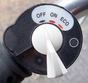
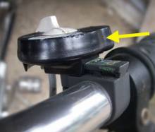
However, before investigating the unit, first consider whether the handlebar control has been exposed to rainwater, as this can cause cutting out and eratic behaviour. Here's how to strip it to dry it out. First remove the bike's battery, then push firmly against the front of the switch body as arrowed right to slide the control off it's handlebar mount.
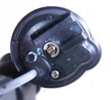
You'll then see the underside of the control shown at the left. With the control upside down, hold the switch white plastic handle firmly in against the body, remove the centre screw and washer and carefully lower the switch handle out of the body, but see below!
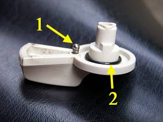
In the handle there's a tiny spring and ball bearing which you see at (1) here. It's a good idea to strip the switch over an old white sheet or similar since these tiny parts are so easily lost. There's a sealing washer against damp at (2).
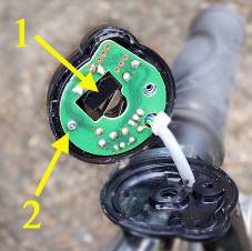
With the spring and ball bearing safe, remove the side screw and you can then separate the top half of the control case. The circuit board shown at the left is now visible and can be wiped and left open for drying. At (1) is a microswitch and in the centre you can see the microswitch operating levers that sit alongside the switch lever centre. The screw at (2) can be removed to wipe and dry the other side of the circuit board if necessary.
To assist with the tiny spring and ball bearing when reassembling, put some thick grease or vaseline on the end of the spring and insert it into it's hole so that the grease holds it in. Now add a spot of grease to the detent recess on the switch body that locates the ball bearing in the "off" position and press the ball bearing into the detent recess. If you now carefully lower the switch handle into the body so that the spring lowers onto the ball bearing, you can gently squeeze it home and hold it secure while replacing the washer and centre screw.
If the control is not the problem and you want to investigate the motor unit, use this link:
Motor Unit Repairs
Motor Unit Repairs