The New Panasonic Motor Unit
The photos in this article result from a collaboration with French pedelec enthusiast Emmanuel. He has a similar website article to my one on the old Panasonic unit but his is on the new unit. Therefore we are exchanging photographs and information so that between us we can cover the new and old units in both languages. This is his website, where you'll also see he has an interesting page on the Sunstar crank drive unit.
This is presented in the form of the differences, physical and operational, from the earlier unit and there is a link to the old unit above to look back at that one's details.
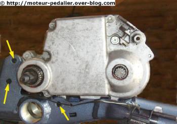
Here's the motor unit unbolted but sitting in the upside down frame. The three arrowed mounting bolt holes surround the pedal shaft where the main thrust is.. The old unit's case had a tall rear arm mounting point which in at least one instance snapped through under pedal pressure, so it's good to see this improvement in strength. This makers frame appears to be an adapted existing one, judging by the vacant bottom bracket hole.
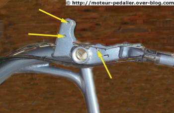
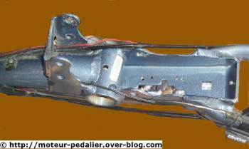
Below there are two views of the motor's frame mounting arrangements, the second one on the right showing the rectangular hole for the battery connector platform support.
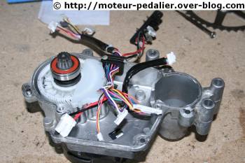
On the right is the left hand side of the unit once the crankcase is parted by removing it's six bolts, the cables disconnected from the right hand half. Note the single nylon reduction gear in place of the multi-stage steel reduction gears of the old unit. Here the gearwheel is shielded by a grease protector plate, but there's more detail later.
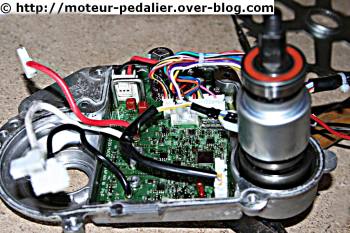
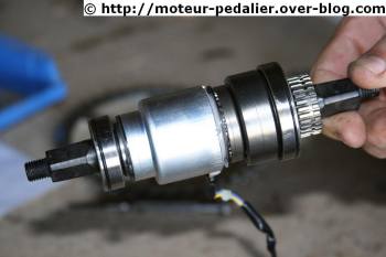
And here is the right hand side with cables connected, the unconnected red, white and black cables with white connectors on the left being the motor phase cables which connect to the motor on the left hand side. The pedal shaft with it's torque sensor and freewheel is seen upright still in place.
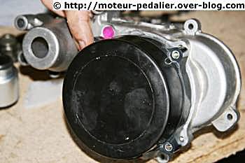
Here you see the same black motor as the old unit, mounted on the left hand casing as before. The pink disc seen just above the motor appears to be a micro-porous water-excluding pressure equalising pad, since this unit is even better sealed than the previous one, as you'll see later.
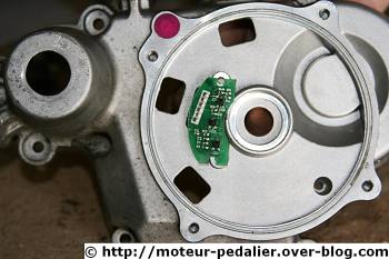
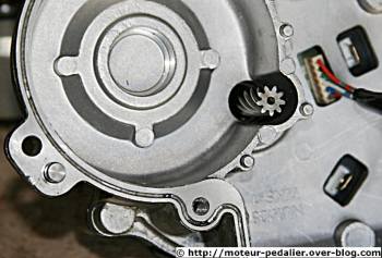
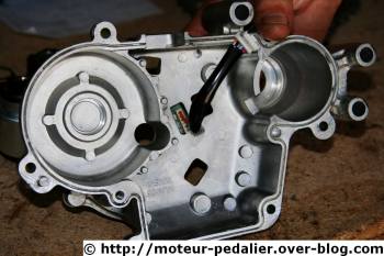
Here's the outside of the left hand crankcase half with the motor removed by four bolts. The motor's Hall sensor circuit board is the same one, but it's mounting arrangement has been much improved. It now has a rear connector and the board mounts on the crankcase wall. The old one mounted rather insecurely on the motor's inside casing making reassembly difficult.
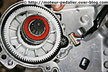
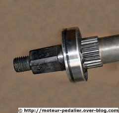
Here's the drive reduction again, this time with grease guard off, showing the motor's helical cut drive shaft. At the centre of the nylon gear is a freewheel on the final drive shaft to enable pedalling with the motor and gears stationary. The tapered splines at the end of the shaft are the chain drive sprocket mounting. This gear reduction arrangement is a great improvement on the old unit for the reasons I've detailed below.
The steel onto a nylon gear makes the unit much quieter than it was with the multi-stage steel gear train of the old unit, and the single stage of reduction makes more efficient use of the motor's output power. In addition, there's a marked gain in efficiency when pedalling without the motor running, since only the output sprocket and shaft on their precision bearings are being turned by the chain. One of the red-wall sealed bearings can be seen on the shaft in the photo above. In the old unit, the freewheel was within the gear prior to the final drive gear, so when pedalling the two gears had to be turned at all times even when the motor wasn't being used, necessitating some efficiency loss.
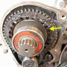
At the left you see a photo of the final drive steel gear of the old unit, with a yellow arrow pointing to one of a ring of 24 magnets. These were read by a Hall sensor at the end of the main circuit board and from their pass rate the road speed was derived for management of the power phase down and final power cut-off. You'll see that these magnets are absent from the nylon gear above. Panasonic have instead derived the road speed from the pulse rate of the motors Hall sensors, utilising them for this second duty, a thoroughly sensible simplification of the system.
This might not meet the approval of tweakers though! On the old unit, it was possible that drilling out every other magnet would double the 9.4 mph first power phase down point and double the 15 mph motor power cut-off. Illegal and very naughty of course!
Here with the nylon gear wheel removed, you can see the helical gear drive cut on the motor shaft. Just beyond on the right is the connector of the Hall sensor board that sits against the motor wall just outside the main crankcase. In turn, to the right beyond that is one of the three blade connectors on the motor wall for the three phase power connections, a second one seen below.
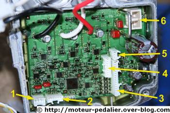
Here's the main circuit board. The black, white and red thick wires are the outputs to the motor phase windings. The numbered and arrowed connectors are for (1) the pedelec torque sensor, (2) the Hall sensor board, (3) to (5) the programming input link, the handlebar control unit, lighting, optional "walk alongside" throttle, possibly varying with series, and (6), the battery connections.
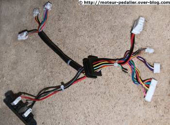
Programming facilities on the old unit were for a small change in power level either way and software updates. I suspect the new unit has the same facilities. The wiring loom with it's sealing grommet is seen here at the right, the upper left connectors for the handlebar control unit, lighting, programming etc. At the lower left is the battery connector platform, while on the right are the internal connections 3 to 6 described above. Numbers (1) and (2) above are internal only connection links.
The pedalshaft with it's integral freewheel, pedelec magnetic torque sensor and it's precision bearings always performed faultlessly on the old unit. Panasonic have wisely retained it completely unchanged. Full details and photos in the old unit article.
On the right you'll see how the flange around the edge of the crankcase halves has a black neoprene strip sealing the case when joined.
And as the photo on the left shows, all the bearings on the shafts emerging from the unit have neoprene sealing rings around their circumference. This thorough sealing makes the unit waterproof even when immersed.
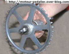
On the left, the 41 tooth chain wheel.
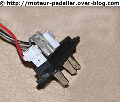
on the right, the three pin battery connector platform.
on the right, the three pin battery connector platform.
Operational notes: The change to a single stage gear reduction has resulted in an increase in the output shaft speed. Since there are limits to the range of standard rear sprockets on hub gear systems, the motor chain drive sprocket has had to be reduced to 9 teeth from the 14 teeth of the old unit. With 28" wheel bikes using a Nexus 7 or 8 gear hub, the rear sprockets are now 22 or 23 tooth to limit the bikes to the legal EU maximum speed in top gear. The chain speed is still slightly higher than on the old unit, so to give comparable cadences the chainring has been increased from 37 to 41 teeth. The smaller chain drive sprocket is likely to wear faster, but Panasonic have simplified it's design and mounting so it's replacement cost should be lower. In addition, the revised mounting makes it's replacement easy as shown in the repairs section linked to below.
The improvements in motor and pedalling efficiency resulting from the single stage nylon reduction gear with it's integral freewheel brings other improvements. Noise is reduced not only by the nylon gear but by the reshaped crankcase which greatly reduces the empty void areas of the old unit and reduces the flat panel areas which could resonate
Further advantages accrue from the simplification of the design, since the cost of maufacture is reduced, making the unit more readily available to bike manufacturers. Since the repair system is still repair by replacement, the cost of that to the consumer is reduced, and the recently quoted price of a unit reflects that, being lower than the old unit some 4 to 5 years ago, creditable when current high exchange rates are considered. However, the sensible redesign is likely to ensure much greater reliability since it has addressed the known problems that occasionally occurred on the old unit.
The High Speed S unit
This unit is fundamentally the same, the mechanical change consisting of an 11 tooth motor drive sprocket in place of the 9 tooth to raise the chain speed and cadence. This would only result in a cut-off speed of just over 18 mph with a standard geared bike so the high speed bikes have the gearing increased by some 16% to raise the cut-off to about 20 mph on a standard gearing system like the Nexus or a single stage derailleur gear system. The start of the motor power phase down is increased to over 13 mph.
In addition the unit is re-programmed to give a higher base power level and the high power mode is increased to a larger multiple of the standard power. Year by year Panasonic having been changing these multiples so a defiitive figure can't be given.
High speed bikes equipped with wide range gear systems like the Rohloff 14 speed hub gear, the NuVinci CVT hub gear, or the SRAM Dual Drive compound gear system have the top assisted speed resulting from the increased gear range of about 25 to 26 mph.
Maintenance and Repairs Section
14.1.2011
.
.