Maintenance, Repairs & Modifications
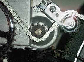
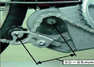
to maintain secure tooth contact. The distance between the spindle centres of the motor and idler sprocket should be 60 to 65 mm as shown right. To achieve that, either adjust the chain by moving the bike's rear wheel within the drop-out slots, or if that doesn't achieve sufficient movement, alter the length of the chain by removing a link or two with a chain tool. For advice on how to use a chain tool to achieve that, see this website.
Later derailleur models have the dual idler wrapper shown at the right, and this is a big improvement which requires no adjustments. A fixed idler follows the motor drive chain sprocket and that is followed by the spring loaded final idler, the spring tension chosen not to interfere with a derailleur rear mechanism's spring loading. Since some hub gear e-bikes had pring loaded idler arms at the rear, they may also have this setup.
Later derailleur models have the dual idler wrapper shown at the right, and this is a big improvement which requires no adjustments. A fixed idler follows the motor drive chain sprocket and that is followed by the spring loaded final idler, the spring tension chosen not to interfere with a derailleur rear mechanism's spring loading. Since some hub gear e-bikes had pring loaded idler arms at the rear, they may also have this setup.
There are no maintenance schedules on the unit and the old units ran for thousands of miles without attention. The much smaller nylon gears in hub motors tend to need regreasing at something over 5000 miles, but the very large gear wheel in this unit should be ok for much more than that. On a high mileage example it could be worth regreasing at 10,000 miles. To do that, disconnect the chain, unplug the unit and remove the securing bolts to detach it from the frame, then remove the six crankcase bolts securing the two halves. Gently part the crankcase halves just enough to expose the large nylon gear and apply a high temperature grease very sparingly to a few points on it's circumference. It will be evenly distributed when running again. Rebolt the crankcase halves, making sure the neoprene sealing strip is still in it's groove around the crankcase half, then reassemble to the bike. The connectors on the wiring loom cannot be mixed up, each is unique to it's matching connector on the bike.
The motor drive sprocket can give chain jumping trouble when it wears, symptoms being a harsh judder and snatching felt through the pedals. Replacement is easy to do as you'll see here. First remove the battery and turn your bike over.
The motor drive sprocket can give chain jumping trouble when it wears, symptoms being a harsh judder and snatching felt through the pedals. Replacement is easy to do as you'll see here. First remove the battery and turn your bike over.
Chain Drive Snatching Problems
Chain Idler Arm Adjustment
Chain Replacement
Diagnosing Drive Snatching
Hand Throttle Modification
Increasing the Power Cut-off cadence
Meter Readout Fluctuating
Motor Drive Sprocket Replacement
Power Cutting Out Intermittently
Chain Idler Arm Adjustment
Chain Replacement
Diagnosing Drive Snatching
Hand Throttle Modification
Increasing the Power Cut-off cadence
Meter Readout Fluctuating
Motor Drive Sprocket Replacement
Power Cutting Out Intermittently
Then with any chainguard removed you'll see the chain drive sprocket between the chainwheel and idler arm wheel. Then either split the chain or move the back wheel forward to give chain slack and remove the chain from the drive sprocket.
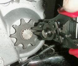
Then you'll be able to remove the securing circlip as shown here and slide the old sprocket off the splines. Fit the new sprocket and replace the circlip, making sure it's securely in it's groove on the splined shaft.
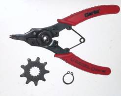
Illustrated on the right is the circlip, sprocket and a typical pair of circlip pliers, obtainable from any good tool shop. If you've never split and joined a chain before and want to know how, go to this webpage.
On older hub gear models chain jumping can also occur on the unit when the earlier idler arm is out of adjustment is out of adjustment. This is not primarily a tensioner, it's function is to maintain the chain wrap around the motor drive sprocket and the arm
A worn chain also causes loss of motor sprocket drive as the chain rides up on the teeth of the chainwheel and drive sprocket, the answer being chain replacement of course. Bikes with hub gears normally use a 1/8" chain, though some manufacturers use derailleur chain and sprockets with hub gears as well, bikes with derailleur gears use 3/32" chain. To check which yours is, measure the width of the chain rollers between the side plates of the links. Fitting a new chain often necessitates fitting a new motor drive sprocket and a new rear sprocket or cassette on the bike, since they all wear together, though the unit's chainwheel isn't affected as often due to it's larger size.
Because of the small size of the motor chain drive sprocket which only has four teeth engaged with the chain during operation, anything associated with it can also cause the chain jumping mentioned above, with similar symptoms. The idler arm pivot bolt should be kept lubricated and the free pivoting action of the idler arm should be checked. In some cases binding has occurred through the tight width fit of the arm on the bolt. JamesC in the pedelecs forum has observed that the shoulder width at the rear of the pivot arm bolt is rather restricted for the arm width and coil spring behind. Removing the bolt and placing a thin small washer behind the shoulder adds enough to the width to allow the arm to move freely without appreciably misaligning the sprocket and chain line.
Because of the small size of the motor chain drive sprocket which only has four teeth engaged with the chain during operation, anything associated with it can also cause the chain jumping mentioned above, with similar symptoms. The idler arm pivot bolt should be kept lubricated and the free pivoting action of the idler arm should be checked. In some cases binding has occurred through the tight width fit of the arm on the bolt. JamesC in the pedelecs forum has observed that the shoulder width at the rear of the pivot arm bolt is rather restricted for the arm width and coil spring behind. Removing the bolt and placing a thin small washer behind the shoulder adds enough to the width to allow the arm to move freely without appreciably misaligning the sprocket and chain line.
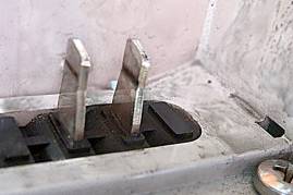
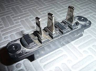
Manufacturing tolerances in frames and battery casings can result in variations in how tightly the battery is locked into place. This in turn can lead to up and down battery movement causing arcing at the battery contacts which can result in intermittent loss of contact and an effect similar to drive snatching or slipping as the power cuts. The photos on the right from Aldby of the pedelecs forum clearly show the contact burn lines, the first with the casings still in place and the second showing the contact strip after removal. A new contact platform should be fitted, which should be obtainable from your bike supplier. After fitting it, adjust the position of the frame lock in it's mounting to minimise battery movement. If necessary, a rectangular pad of a thin material like plastic or rubber sheet could be placed in the battery well to take up any slack, with the lock mounting adjusted afterwards to take up the slack.
For the optimum battery mounting security the advice of JamesC of the pedelecs forum should be followed. First adjust the battery lock so that it sits high in it's mounting pad, relieving it's small mounting bolt from undue pressure. Then make sure the three motor mounting bolts are tight in the frame, following the procedure in the running in section. Finally add layers of a thin rubber cut-out such as cut from old inner tubes into the battery well, using sufficient to ensure all movement is removed while still allowing the battery to be inserted and locked with ease. About two layers will usually be enough.
Fluctuations between three and one LEDs illuminated on the handlebar battery meter during steady riding can also be caused by battery mounting looseness as contact is lost, particularly on bumpy roads. If this occurs, follow the procedure above to cure it.
When drive snatch or apparent slippage occurs, it can be very difficult to tell exactly what the cause is from the many possibilities. However, here is a simple procedure to help determine the cause. First, with a hub gear bike, ride the bike to a slight incline, then with the power switched off, stand on the pedals and start climbing the slope using as much pedal force as possible. If the drive slips it's likely to be the hub gear that's failing. If your bike has a derailleur gear, that's unlikely to be cause of slipping unless on the small top gear sprocket if it's excessively worn, allowing the chain to jump over the teeth.
If that doesn't cause the snatching or slipping, try riding the bike in standard power mode on a flat but bumpy stretch of road, using the minimum pedal force to maintain a moderate speed. If the power tends to still cut in and out, it could be the battery movement intermittently losing contact and cutting the current.
If that still didn't cause the problem, it's going to be slippage of the chain over the motor drive sprocket that's causing the problem. On a hub gear bike, first adjust the idler arm angle and distance so that it's set according to the the instructions above. With that done, ride the hub gear or derailleur bike in top gear using High Power mode up a slope using maximum pedal force at a slow speed, below 10 mph. If the slipping is quite severe then, it's likely to be wear on the motor drive sprocket and or chain allowing the chain to rise and jump the sprocket teeth.
Reverse the motor drive sprocket on it's mounting splines to present an unworn face to the drive face of the chain rollers and recheck for slippage in high power mode as above. If the slipping stops, it's the worn motor sprocket that's the cause. If it still slips, it's the wear on the chain and sprocket combination that's causing the problem. In any case, it's usually advisable to change most of the transission set, the chain and both motor and rear hub sprockets. The chainwheel isn't usually a problem until quite old.
Pre 2011 Panasonic drive units often give the maximum power up to a cadence (crank rotations per minute) of 39, which is a quite slow pedalling rate, well below the optimum for efficiency and knee joint health, and those with prior cycling experience can find this a problem. This can be alleviated to some extent by fitting an 11 tooth chain drive sprocket in place of the 9 tooth, this increasing the point at which power starts to phase down to a cadence of 48. Of course, when done in isolation, these increase the speed at which power phase down commences to 11.5 mph and the power cut-off speed to 18.3 mph, which in turn will reduce the range since the motor will be running for more of the cycling time. Many prefer that, but those speed increases can be reduced by changing the hub gear rear sprocket or cassette top gear sprocket. Newer 2010/2011 units often have a 35 tooth chainwheel in place of the older 41 tooth and different rear sprockets to match, so some of this does not apply to them. Some of the speeds in the following two paragraphs are for the 700c/28" wheels that are mostly used on these bikes, but the speeds for 26" wheels are in green and appended in brackets.
With a Nexus 7 or 8 speed hub, it won't be possible to get the speed of power cut-off back down to 15 mph, since large enough sprockets are not available. The largest normally available is 24 teeth, which will only bring the speed with a Nexus 7 down to 16.8 mph/27 kph (15.6 mph/25 kph), with a Nexus 8 speed (any model) down to 17.6 mph/28 kph (16.3 mph/26 kph). An additional advantage of using the 11 tooth sprocket is that the consistency of the chain drive over the sprocket is much improved, there being much less chance of drive slipping problems as well as less sprocket wear. The 11 tooth chain drive sprockets can be purchased in the UK from 50cycles.
The standard unit power phase down starts at 9.4 mph, steadily reducing to the legal power cut-off at 15 mph. Those speed points can be raised by changing the hub gear rear sprocket to a smaller size or the derailleur cassette to one with smaller sprockets. The maximum speed points with Nexus hub gears are with a 16 tooth rear sprocket, giving with the 7 speed hub 12.9 mph/19 kph (12 mph/18 kph*) and cut-off at 20.6 mph/33 kph (19 mph/31 kph*) respectively, and with the 8 speed hubs, 13.5 mph and 21.5 mph respectively. Such extreme changes can reduce the range greatly, typically a 30 mile/48 kilometre normal range can drop to as low as 18 miles/29 kilometres. Intermediate changes such as sprockets of 19 to 17 teeth might be preferred, the change in speeds and ranges can be calculated pro-rata. ( *for 26" wheels in green)
Typically on a derailleur equipped bike, the cassette is more restrictive in how far the phase down and cut-off speeds can be increased. A cassette with a normal top gear sprocket of 13 teeth when changed to an 11 tooth will give respective speeds of 11.1 mph and 17.7 mph. It's not advisable to use smaller than an 11 tooth sprocket since the wear could be unacceptably high with both rider and motor power transmitted through it. Remember that hill climb ability is also affected by raising the gearing, though the effect of this is much less with the Panasonic system due to it's power delivery characteristic.
The only matter of concern during the initial period of ownership is the tightness of the three motor mounting bolts. Because frames are painted and the motor is clamped between side plates on the frame, pedal pressure tending to rock the unit compresses the paint layer, often leaving the motor mounting slack after a while. After riding your bike for between 100 to 300 miles, tighten the three mounting bolts, their positions shown arrowed on this inverted frame photo. The bolts should be very tight, preferably use a torque wrench and tighten to about 30 to 35 lbs/ft (41 to 47 Nm). Thereafter an annual check of their security is advisable, or bi-annual for a high mileage or very strong cyclist.
A hand throttle option is available for these Panasonic unit bikes, but this is widely misunderstood. It is not an alternative to pedelec when riding, it's only intended as a "walk-alongside" throttle for use when a hill is too steep for an owner to ride up it. Therefore it's maximum speed conforms to the pedestrian controlled electric vehicle regulations, 4 mph (UK) and 6 kph (EU). Because the pedelec torque sensor is not in use when walking alongside with the hand throttle, the power is at a minimum, and many users in the steepest hill areas find it's power insufficient to be really useful, only helping rather than propelling the bike's weight independently. There is an anomaly when the hand throttle is fitted to a bike with the "S" type high speed unit though. Because those units have their maximum speed increased to the 20 to 25 mph region, depending on gearset fitted, the hand throttle speed is also greatly increased, typically to around 12 to 13 mph (19 to 20 kph). This means they can be ridden with the throttle in use.
Pedelecs forum member Fecn has investigated the throttle and reports that it's a very simple variable resistor based unit containing only a 3/4 turn 10K variable resistor and a spring to return the thumb lever back to place. Only a small portion of the resistor range is used, the throttle-off position corresponding to a resistance of 1.3kOhm, and the on position giving a resistance of 2.5kOhm. He suspects that they've got this wired to a logic level output somewhere inside the Panasonic unit so they can fake the 'pedals are turning' signal regardless of the pedelec sensor.
Updated 21.11.15
.
.
If you only want to grease the internal gears you don't have to do any of the stripping down. You don't even have to remove the unit from the bike.
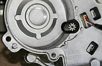
In the hole at the centre of the motor mounting circle you'll see the edge of the nylon gear. Use a screwdriver blade to dab a little general pupose grease onto the gear teeth at that point. Then turn the bike's back wheel backwards slightly which will rotate that nylon gear a bit. Then dab a touch more grease onto the teeth. Continue doing that until the nylon gear has a little grease at several points around it.
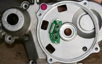
First turn over the bike, then just remove the four bolts holding the motor onto the left side of the crankcase and pull off the motor. The motor is sometimes a bit stuck onto the crankcase wall so you might need to tap the edges of it's mounting base with a mallet or hammer to free the bond.
You'll then see the view in the photograph on the right.
You'll then see the view in the photograph on the right.
Finally grease the helical spline grooves of the motor shaft (which you see in the photo on the right with motor fitted), then refit the motor. The motor shaft rotation will distribute the grease around the large nylon gear.
Since as you can see in the photo on the right the gears run in a sealed chamber, no grease will permeate any sensitive areas of the crankcase.
Since as you can see in the photo on the right the gears run in a sealed chamber, no grease will permeate any sensitive areas of the crankcase.